I need to make picture frames for the marquetry and parquetry pieces made in class. I was fretting about how to make sure the angles and lengths of the frame pieces were correct. I found a video online (MakeSomething) that shows how to make a simple jig taking care of these two failure modes. The jig is essentially a table saw sled with two straight edges at 45° with a stop on one edge.
Watched the full lunar eclipse this morning. It is the last until March of 2025.

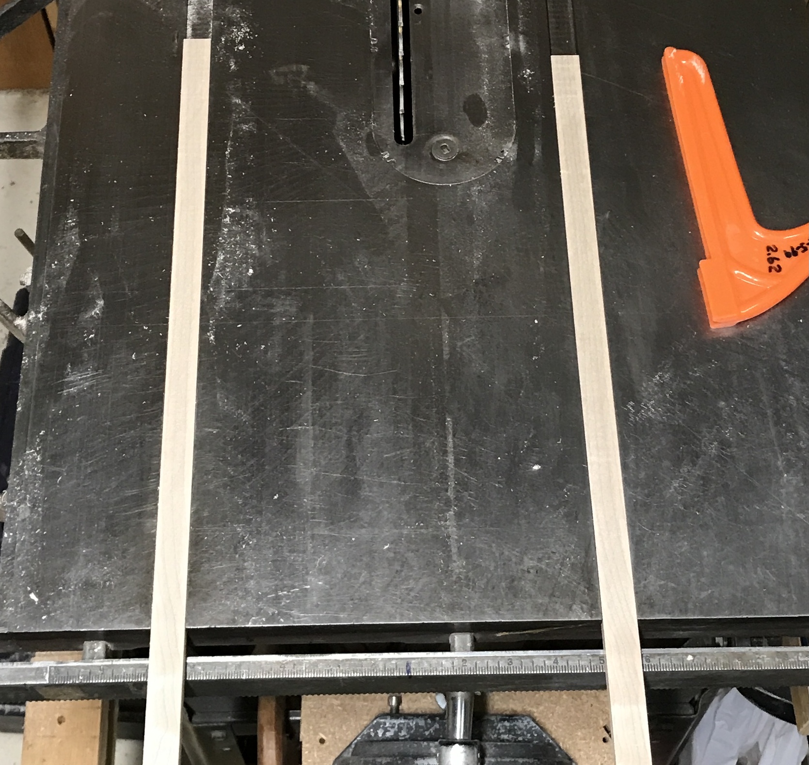
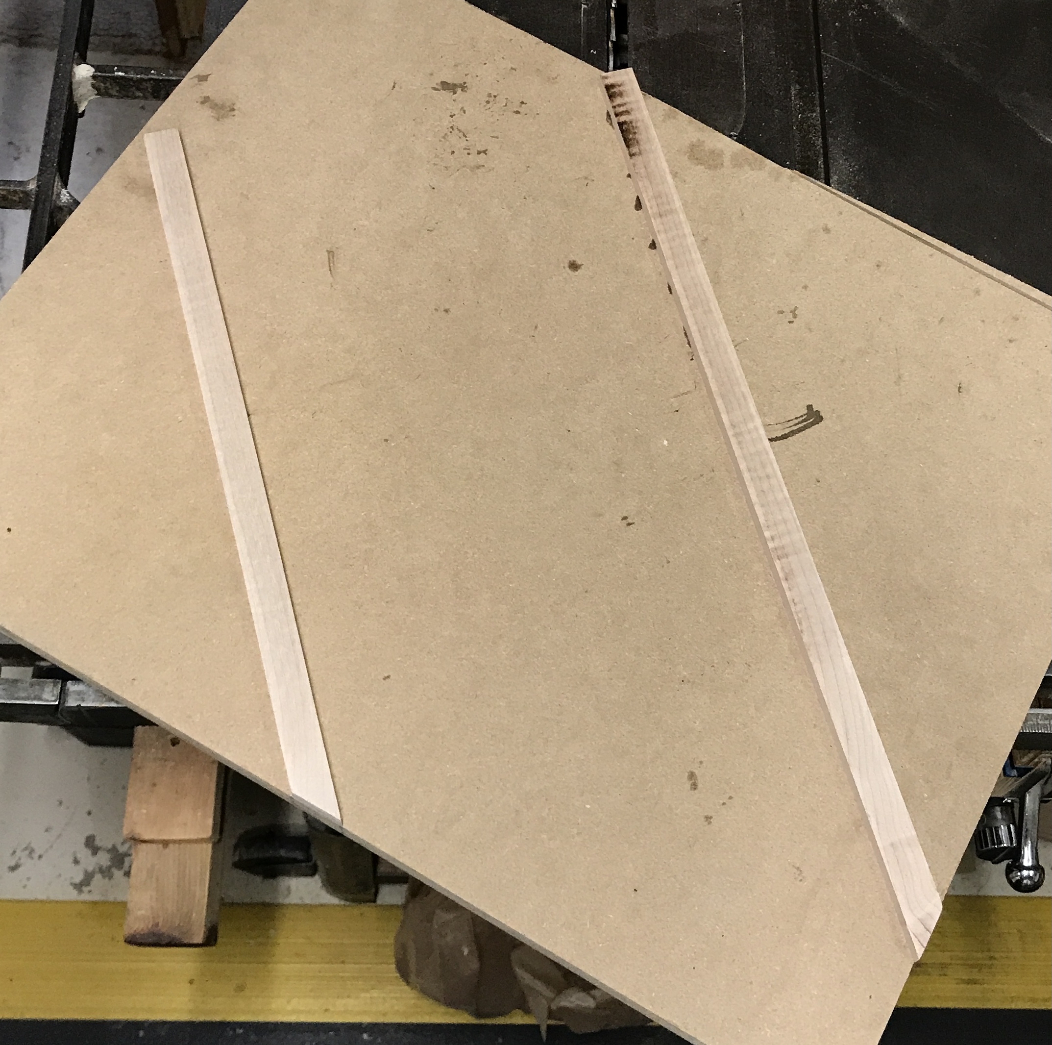
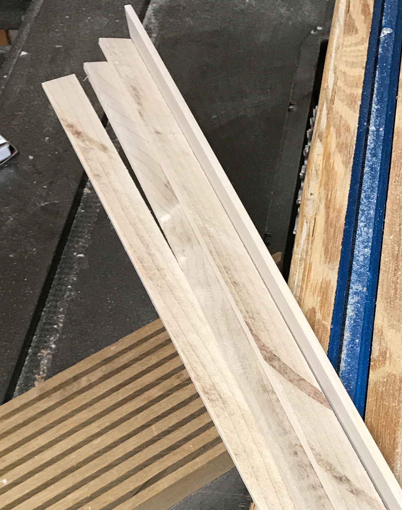
A 18" X 22" piece of 3/4" MDF was located in the garage. The first task was making rails for the jig. Two pieces of 3/8" X 3/4" hard maple were cut. These were shaved on the table saw until they fit smoothly in the table's slots. The MDF was aligned over these rails sitting in the table's slots so one corner was aligned with the blade and the board was set at 45°. The latter was done with the speed square. The board was marked for the rails and removed. Gorilla CA glue dots were put on the rails and the board returned. It was aligned with the marks and a weight was set on it.
After drying for ten minutes the table was marked and drilled for #6 X 3/4" screws. These were inserted. The rails were then waxed with Johnson's paste wax. The jig was placed in position and a kerf was cut about 4" into the corner. The framer's square needs to sit above the sled. Four lengths of 1/8" hard maple were cut from a scrap. These were epoxied to the framer's square and clamped.
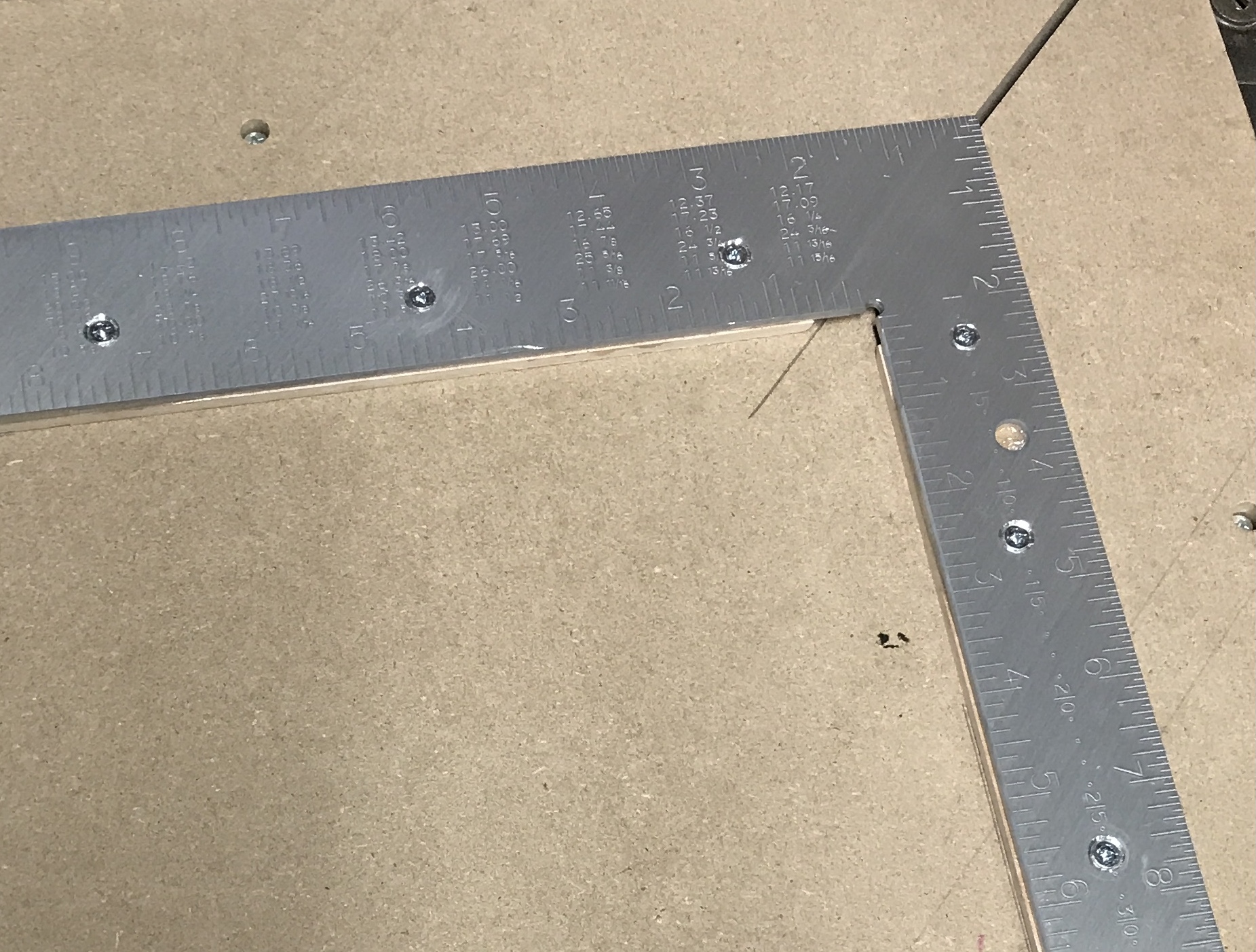
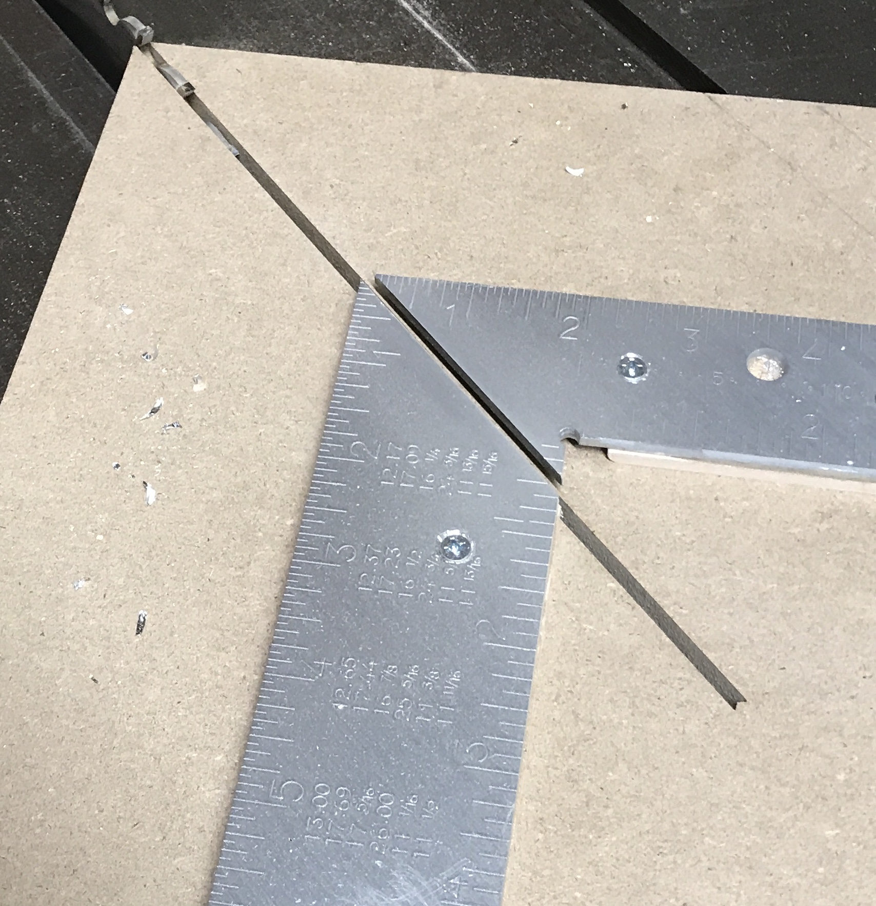
After drying overnight the framers square was marked, punched and drilled about every 3". The holes were heavily chamfered. The framing square was carefully aligned so that it is 45° to the table slots. Holes were marked and drilled into the MDF. #8 X 5/8" screws were used to hold it in place. Screwing into MDF is probably not the best path, but it worked for now. The kerf cut previously made in the MDF was continued (slowly) through the framing square.
A strip of 120 grit sandpaper was sprayed with contact cement. It was glued to the side of the jig next to the long arm of the square. A scrap of wood was located for use as a stop block. A dado was cut in this block along one edge. The dado was about 1/8" up from the bottom, 1/8" wide, and 3/8" deep. The block was cut at 45° using the jig in its current state. It was cut off at about 6". A horizontal toggle clamp was purchased yesterday. It required some modification. It is set up with a 5/16" bolt with NF threads. I had nothing to match it, so switched it for a 5/16" toilet bolt with 18 TPI. The toggle clamp was screwed to the stop block with four screws.
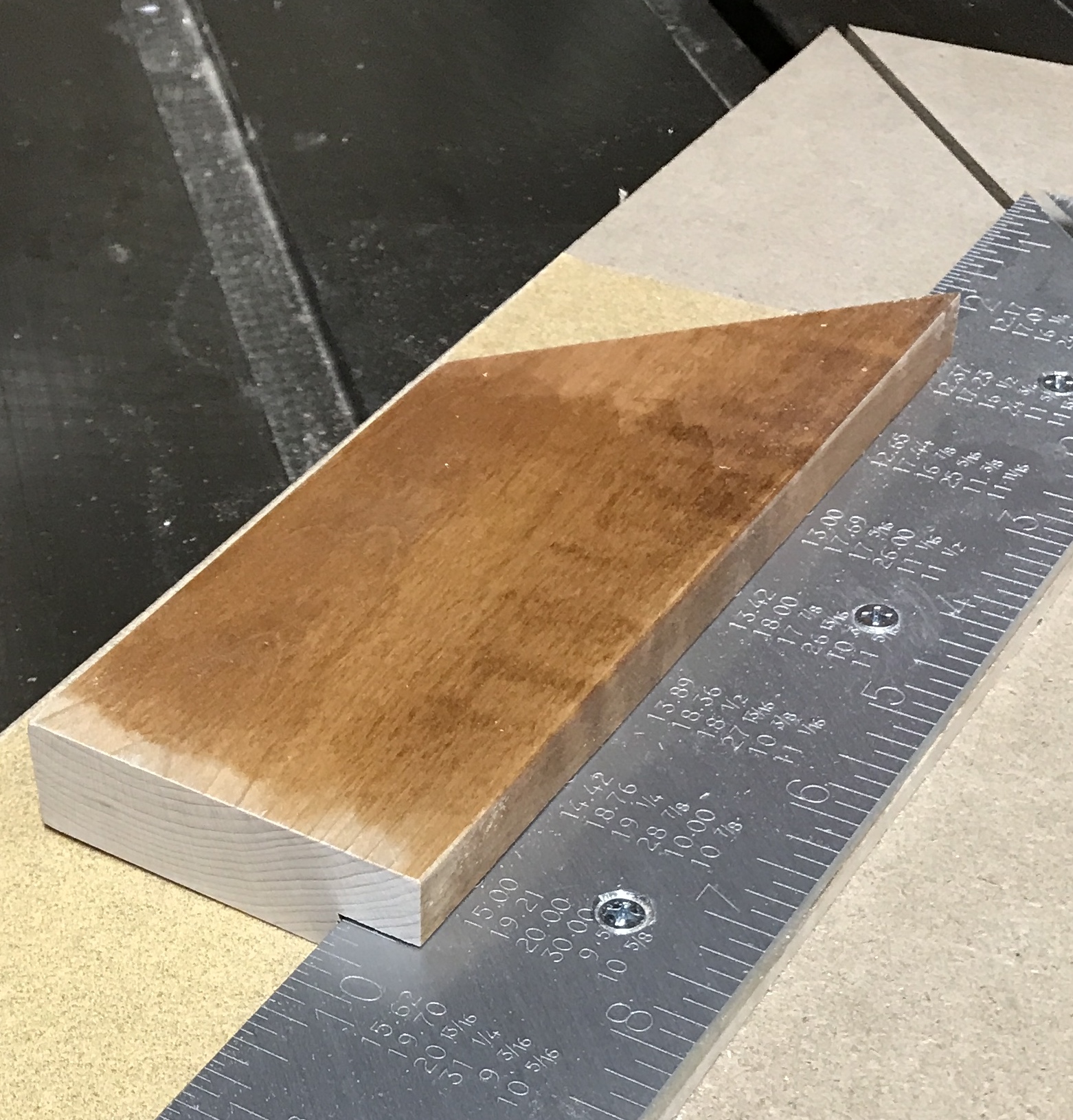
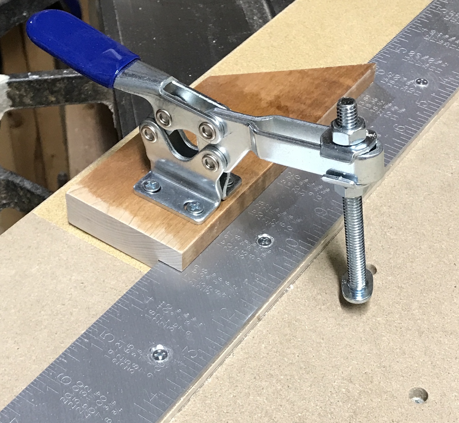
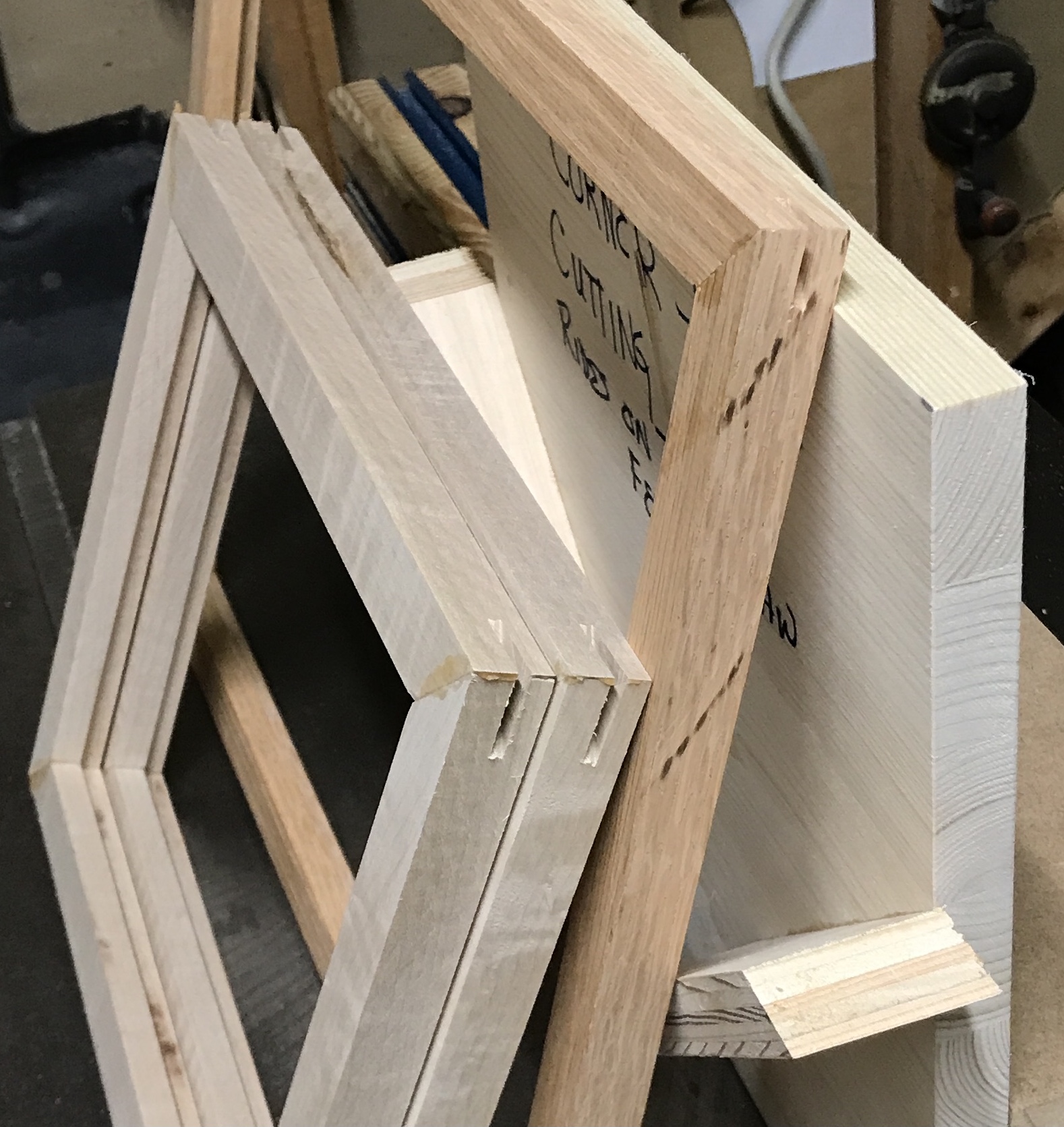
With everything completed the jig was ready to use. I had two lengths of red oak about 1" X 3/4". They both had a rabbet cut into one corner about 1/4" X 3/8". The end was cut off of one strip at 45° using the short arm of the square. The stop block was set at 12 1/16". The angled end was pressed against the stop block and the second cut was made producing the first side. This was repeated to make an identical copy. The toggle clamp could not be used for the 16" long side. The clamp is set too far back from the miter and is no longer supported by the table. A different clamping arrangement was used. The second two sides were cut. The parquetry piece did not quite fit. This was corrected by deepening the rabbets in all four pieces.
The measurements above were not wrong. There is a minor flaw in the construction of the jig. The 1/8" kerf cut was centered on the corner of the framing square. This means that ~1/16" of each side of the square was removed. Consequently, instead of adding 1/16" to the picture size to set the stop, 1/8" needs to be added.
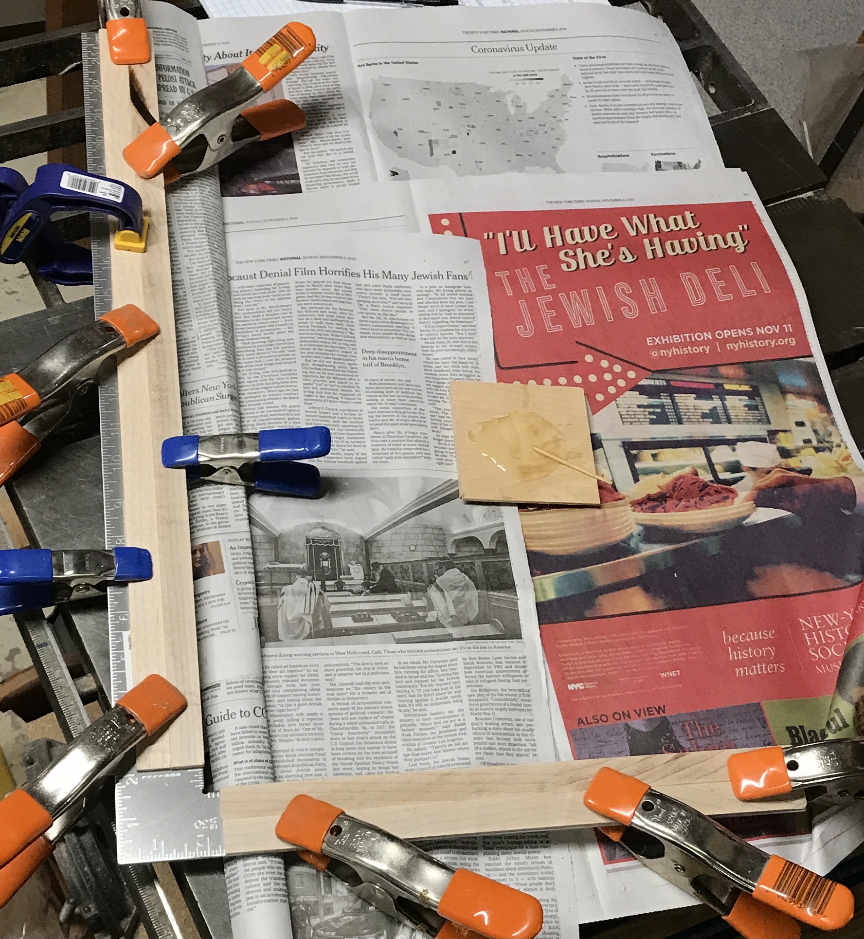
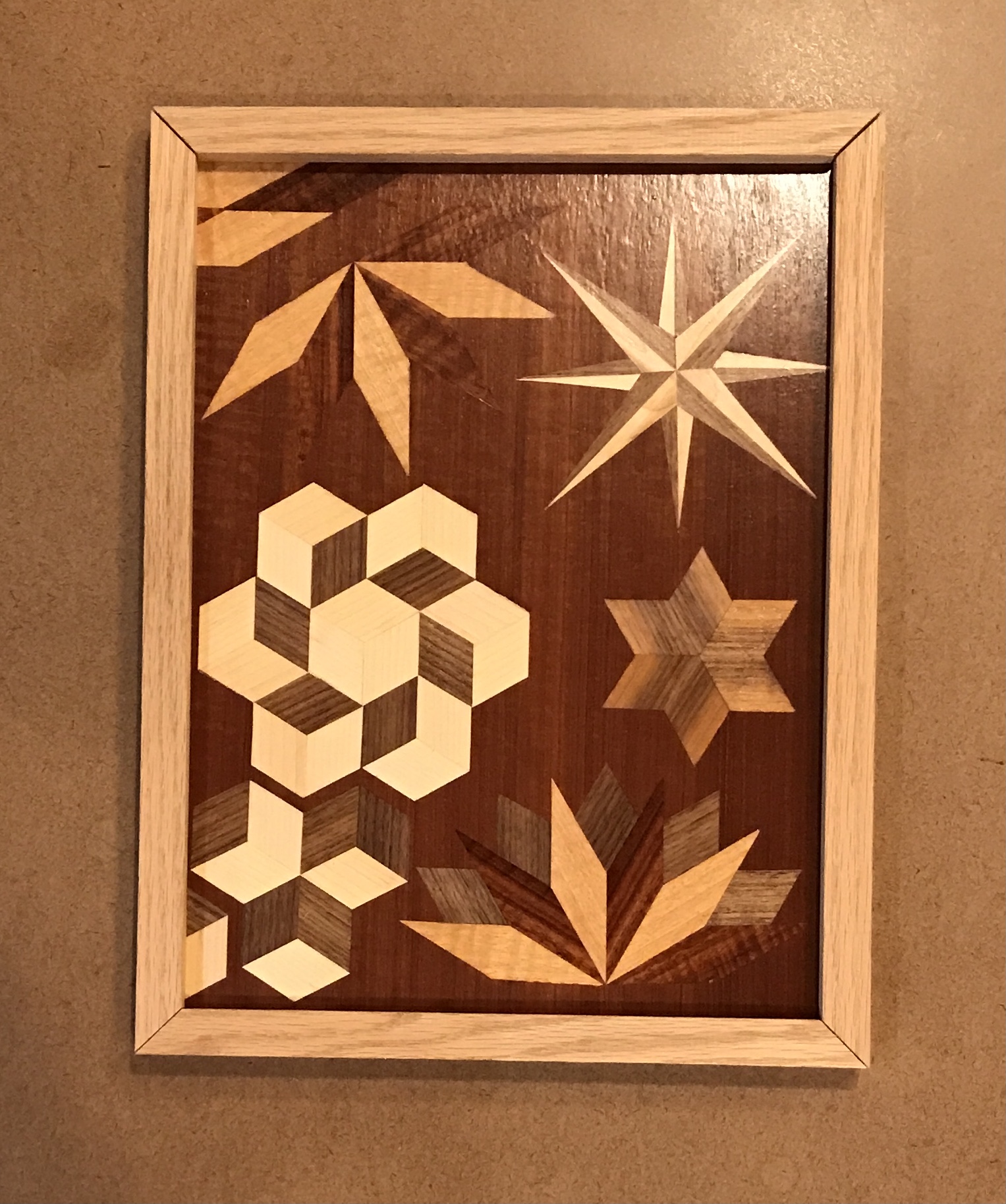
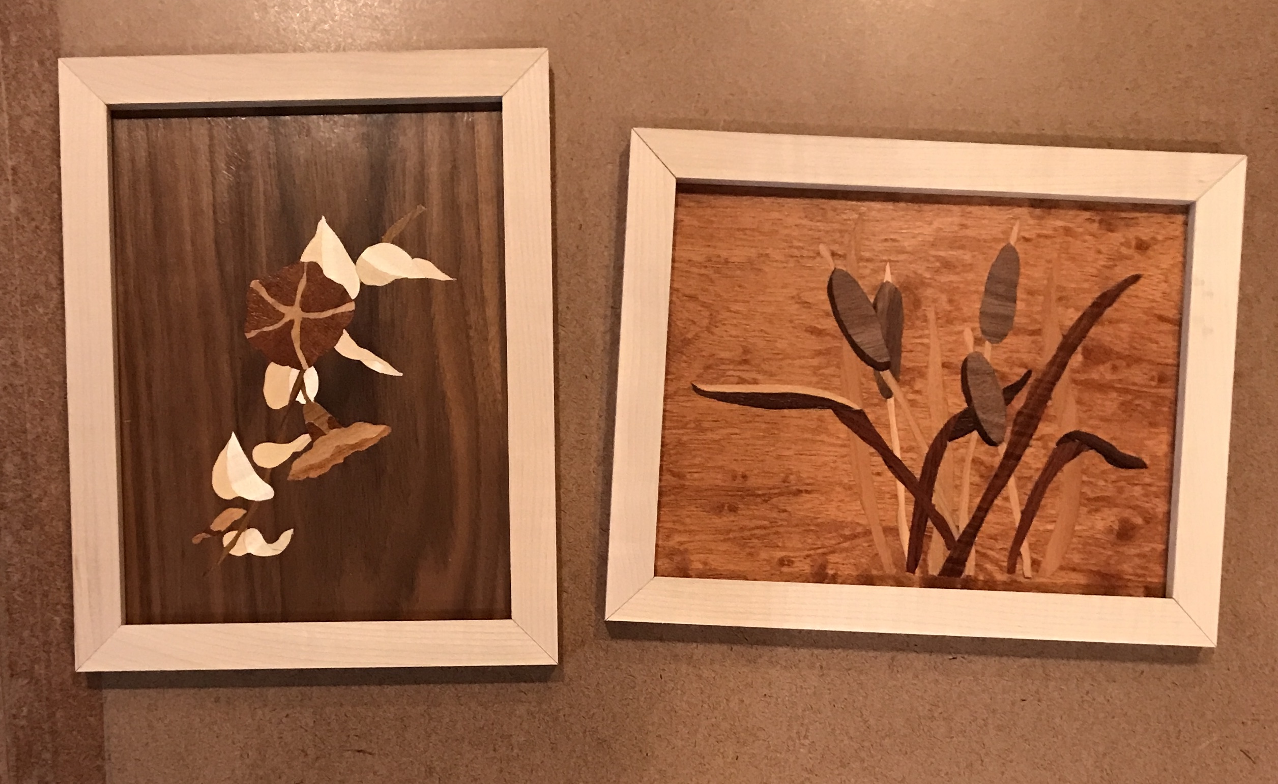
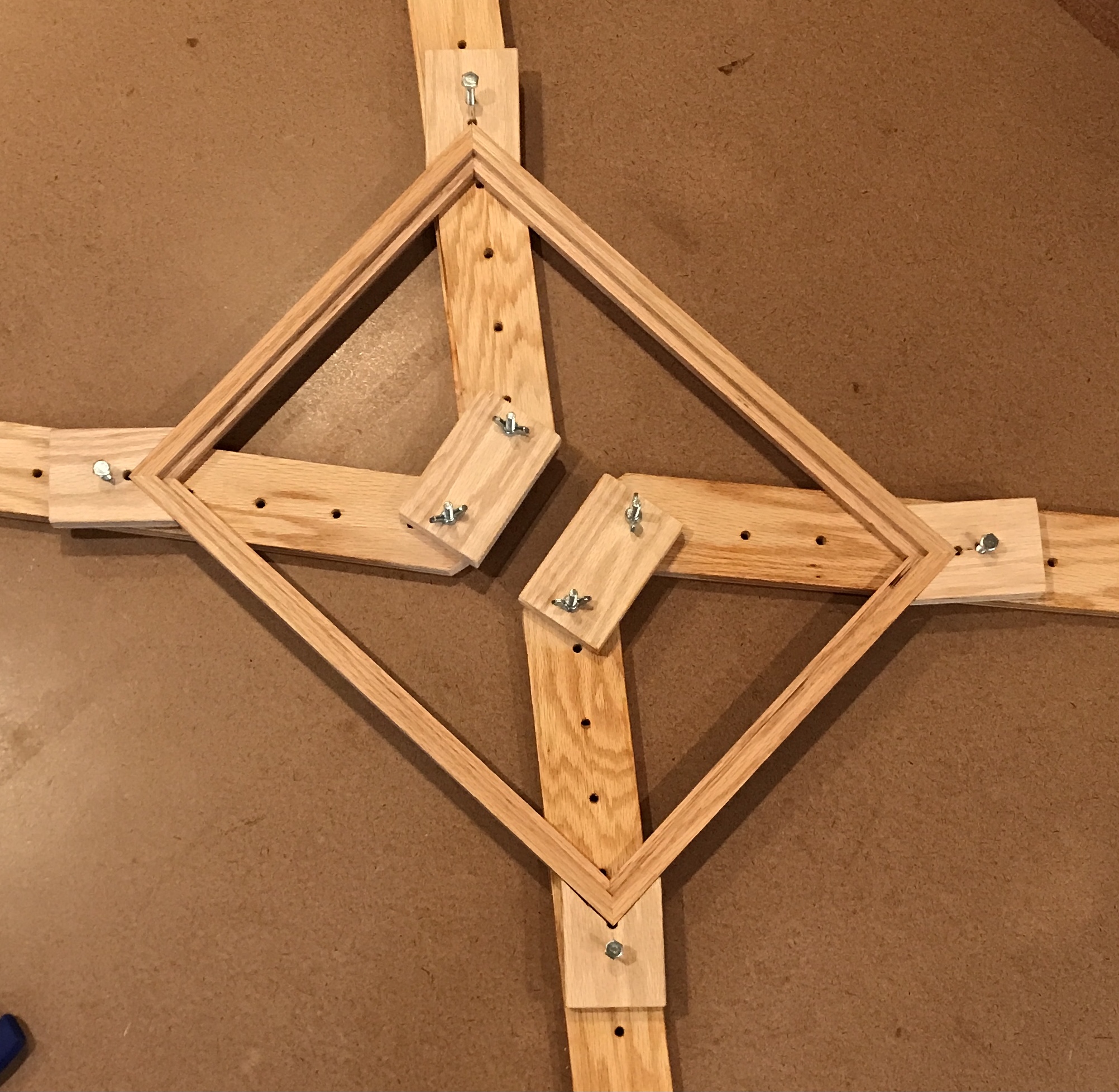
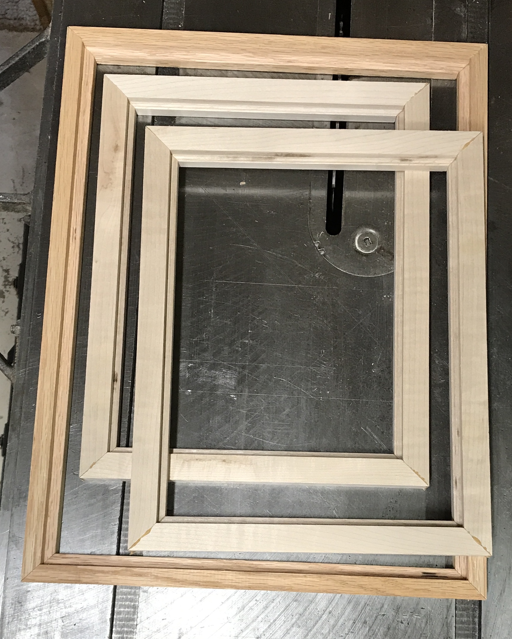
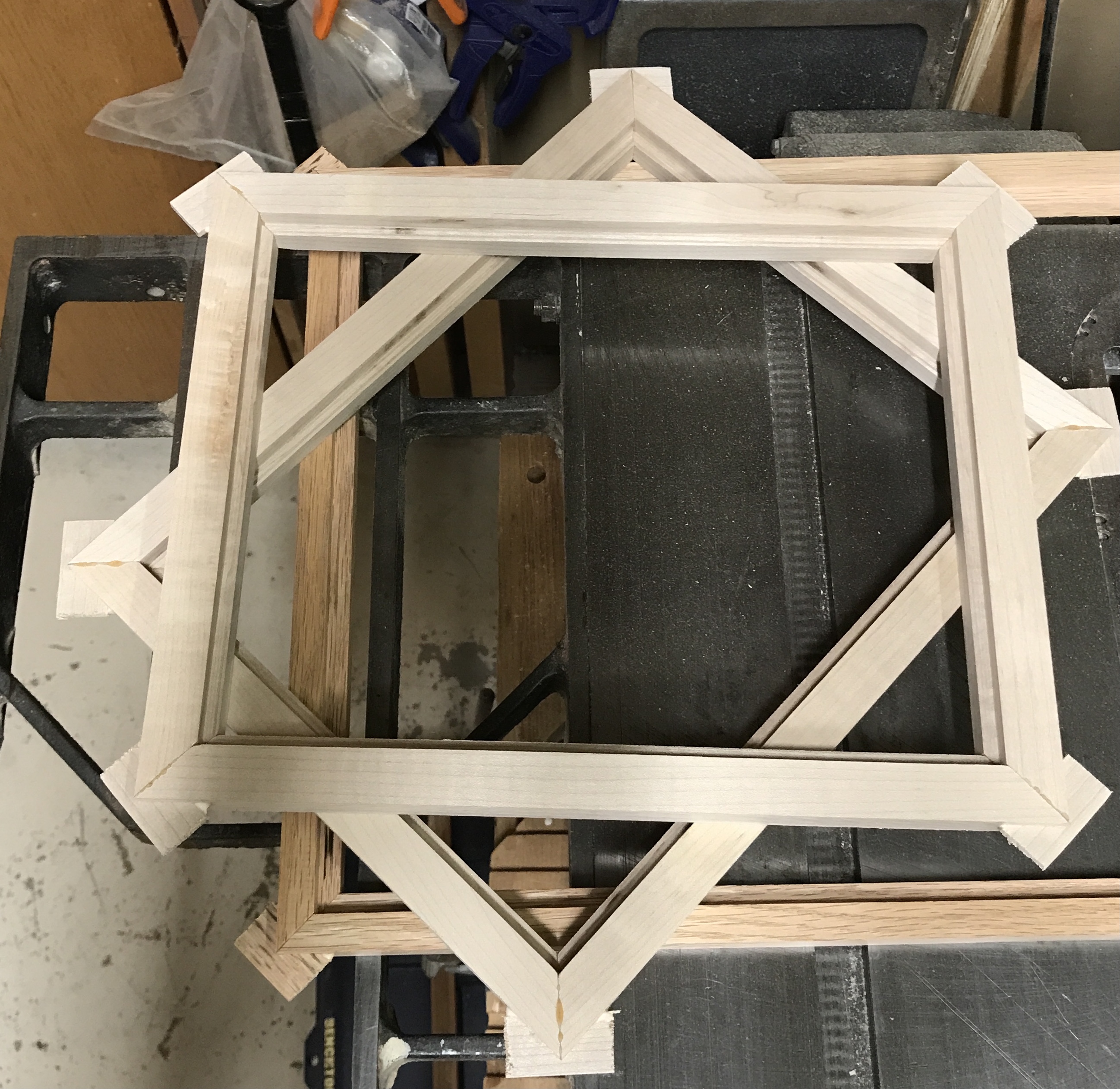
Some hard maple was used for the two marquetry pieces. Again two pieces about 3/4" X 7/8" were cut. Rabbets were cut along their length. The rabbet was held against the short side of the frame and the 45° angle was cut. The stop was set at 8 5/8" for the 8 1/2" long piece. Four short sides were made. The long sides were made similarly, but cut with the stop set at 11 1/8". The frames arranged around the marquetry pieces are shown below.
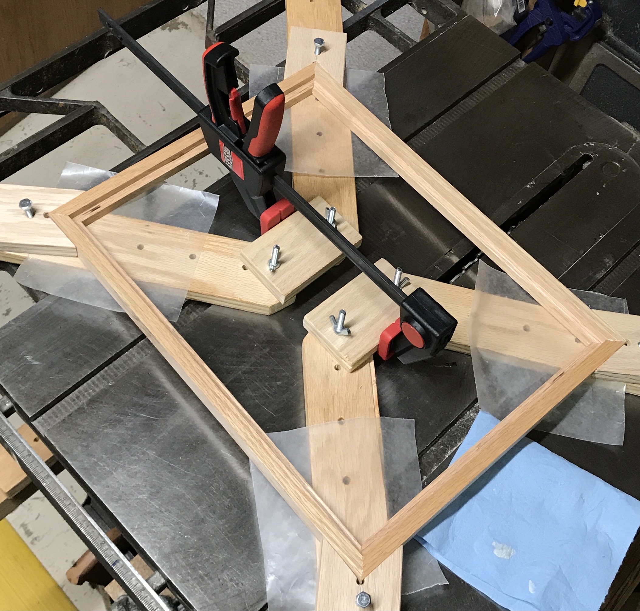
Now a frame clamp is needed. From the same video author as above, this frame clamp is about as straightforward as can be. It has four legs. Two pairs of legs are connected at one end making two hinged vees. Holes are drilled through these legs every inch or two. These holes hold the corner clamps.
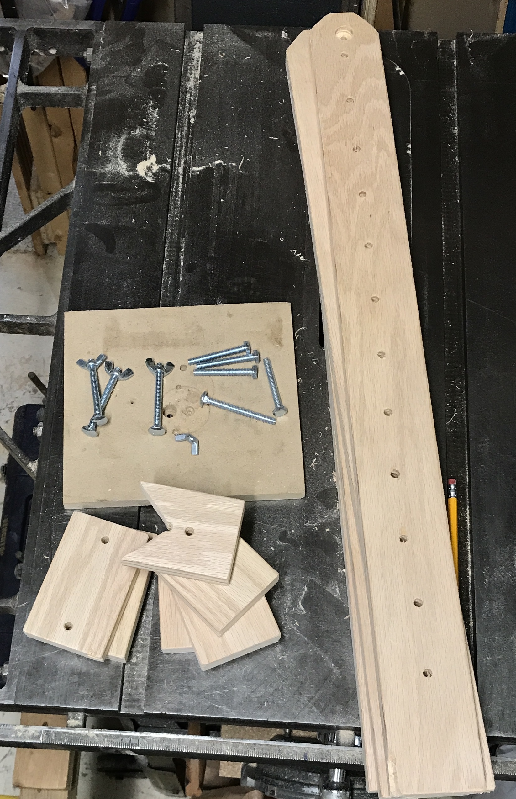
A rectangle of plywood was used for all of the parts. Four 26" lengths were cut 2 1/2" wide. A fifth 2 1/2" wide board from the plywood was cut into two 5" lengths and four 4" lengths. The legs were marked for drilling and drilled every 2" with a 1/4" bit. The first hole in each leg was 1" from the end and 1" from the second hole. The back side of these first holes were countersunk for the carriage bolts. Circles were marked on the ends of these legs. The corners were cut off to mimic a round end. All of the boards' edges were chamfered in some fashion. The legs were waxed with Johnson's paste wax.
The two 5" lengths were drilled on center 3/4" in from each end with a 1/4" drill. All edges of these parts were also chamfered. The four smaller pieces were drilled first at 1 1/4" from one end. A second hole was also drilled about 1" further in from the first hole. A square end was used to mark these blocks for cutting. The right angle was cut out on the scroll saw. Again all of the edges were softened. All of the parts of this clamping jig are shown in the photo below. A mock up with frame in place is also shown. (The center connectors will be clamped pulling the whole thing tight.)
Unfortunately, the 6" bar clamp I have is not large enough for the big frame. The parallel clamps are large enough, but the handles are in line with the jaws and won't fit inside the frame. Off to Menards to purchase a larger clamp.
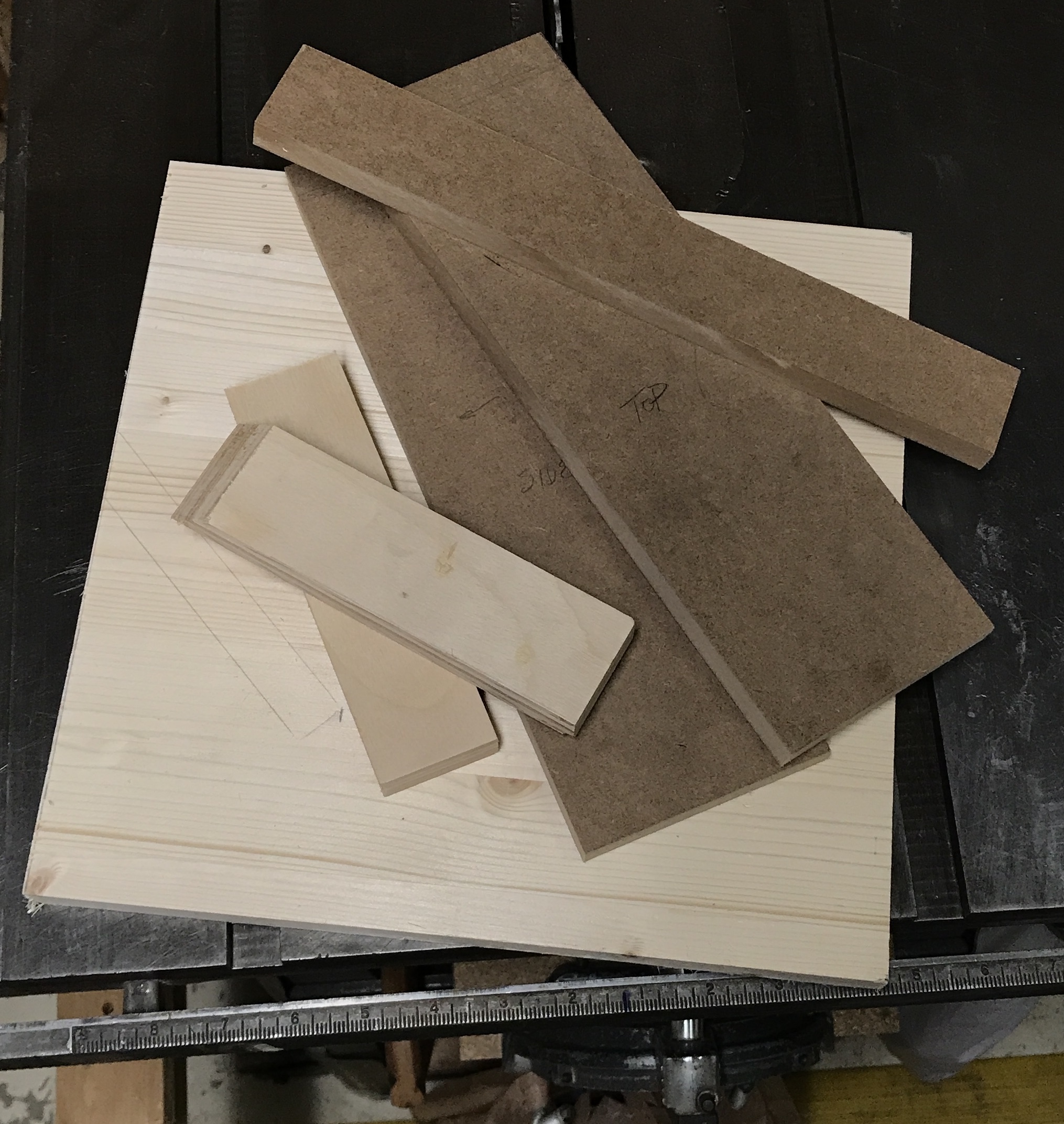
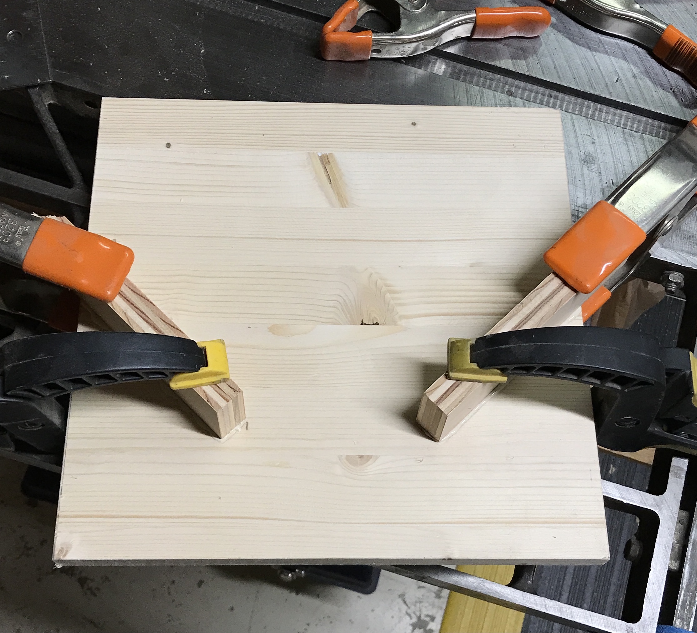
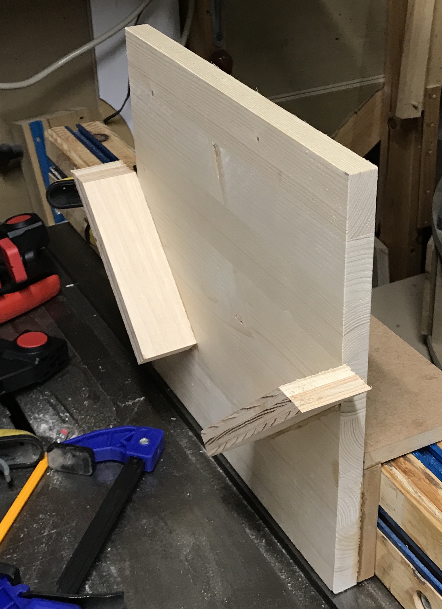
The frame corners will be splined, so a corner splining jig is needed! This spline cutting jig will be a box that slides over the table saw fence with an attached frame with two boards set at 45° angles to the frame. A 3/4" X 12" X 12" pine board was cut from scrap. A 1' length of 3/4" plywood was cut in half at a 45° angle. A scrap of MDF yielded three boards for the box. One side is 3 3/4" wide, the second side is 2" wide, and the top is 3 7/8" wide. The two boards on the frame were glued and clamped with a square between them. The arms of the square were set to the same distance from the bottom edge of the board. The three MDF boards were glued as well. The photos show the parts and both glue-ups.
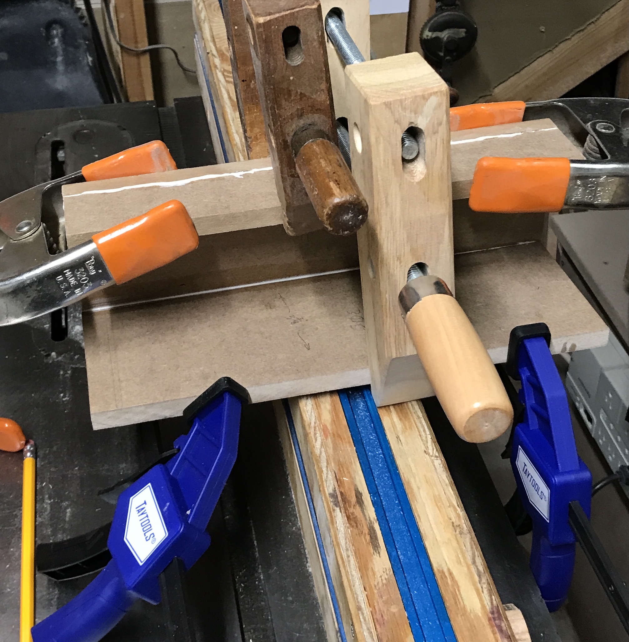
After the glue set on these parts the box was glued to the back of the frame completing the corner spline cutting jig. It is a nice tight sliding fit on the fence.
Glued up the frame for the marquetry piece this morning after a short stint outside in the freezing cold to put the winter cover on the patio's loveseat. Plan to glue up all three frames and spline the corners today. The second photo shows the three frames after glue-up.
The spline cutting jig was put in place on the fence. The fence was adjusted so there was 3/8" between the blade and the jig. The blade was raised so it was about 1/2" above the corner of a frame placed in the jig. The four corners of the large oak frame were cut. The blade was adjusted and the eight corners of the two small maple frames were cut. Splines were made from scraps of oak and maple. Some sanding with the belt sander was needed to achieve the correct thickness. Glue was applied in the cut with a toothpick. The splines were inserted, sometimes needing a few taps with the mallet. The pictures below show the cuts and the matching splines glued into the corners.
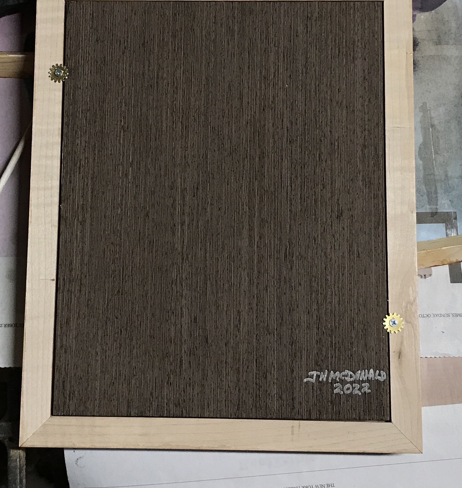
The splines were sawed off, care taken to leave the stumps proud. These were sanded off with an 80 grit sanding block. The outer sides and the insides were sanded to 220. The front faces were scraped. After removing the dust all three frames were varnished. Two coats were deemed sufficient. Instead of washers and screws to hold the pictures in the frames, gears were used. These were the poorly formed gears left over from the business card project. Holes were drilled for #4 wood screws. The gears were screwed into place in two places for each frame as shown in the photo below.